1. Introduction
A virtual power plant (VPP) is an aggregated cluster of heterogenous distributed energy resources (DERs), controllable loads, and distributed energy storage systems (DESDs) that form a single virtual generating unit. The solitary operation of DER units does not have sufficient technical and cost-effective feasibilities to participate in system management and market-based activities. However, with the vision of VPP model, power flows can be coordinated among the widely distributed DERs, controllable loads, and DESDs optimally through effective energy management system (EMS). That enables decentralized system management easy for the higher proliferation of small- and medium-sized renewable energy resources in the grid [
1].
A lot of research has been previously done on designing optimal control strategies, economic dispatch, and management of VPPs [
2,
3,
4,
5]. However, less attention is paid towards the underlying communication required in implementing different strategies. In [
6] and [
7], authors provided optimal dispatch and distributed energy management strategies with limited communication requirements. In both studies, details of the communication aspect were not discussed. Similarly, in [
8], authors presented interaction and information exchange sequences between different components of service centric VPP and market aggregators for electricity market participation. However, the communication requirements for implementing those information exchanges were not discussed.
For the effective and stable operation of VPPs, a robust, reliable, interoperable, secure, and standardized communication protocols are required [
9,
10,
11]. Authors in [
10] demonstrated the impact of time varying topology of VPP on the communication network. Furthermore, the impact of communication delays and noises are also discussed. In [
11], authors presented the performance evaluation of the VPP communication network in terms of latency, packet loss, retransmissions, and bandwidth.
Recently, researchers have proposed different standards for VPP communication, such as IEC 60870-5-104 [
12], OpenADR 2.0b [
13], and IEC 61850 [
14]. VHPready (short for Virtual Heat and Power Ready) [
15] is an open industry standard based on IEC 60870-5-104, which was proposed for VPP communication [
16]. Authors in [
16] proposed an OpenADR 2.0b protocol for the reliable operation of DERs and automated electric vehicles in VPP. In [
17] and [
18], VPP communication based on IEC 61850 information models is presented. The object-oriented interoperable information model of IEC 61850 makes it a front-runner and the most popular standard for VPP communication [
18].
The susceptibility of VPP communication to cyber-attacks and its impact is discussed in [
19]. Further, to mitigate this problem, an attack-robust distributed economic dispatch strategy is proposed in [
16]. However, for a secure and reliable operation, it is expected that the communication protocol must provide security towards any cyberattacks. Further, due to large presence of intermittent DERs in VPP, its topology is highly time varying. The communication protocol employed for VPP communication must have the capability to address the scalability issue. Most of the communication standards proposed for VPP communication in literature do not have the capability to address these issues of scalability and security.
To address this problem of scalability and security in IEC 61850 communication for smart grids, the IEC 61850-80-3 [
20] recommends eXtensible Message Presence Protocol (XMPP) [
21] web protocol as a middleware solution for IEC 61850 communication in smart grids, as XMPP protocol provides high network scalability, robust security mechanisms, and decentralized architecture. Further, a recently published standard IEC 61850-8-2 [
22] provides the specifications for mapping IEC 61850 MMS and time synchronization messages to XMPP. In [
23], authors presented the mapping of GOOSE and SV messages to XMPP protocol. In [
24], a prototype implementation of IEC 61850 traffic over XMPP was demonstrated for local and wide area networks. Similarly, in [
25], authors developed an edge gateway based on IEC 61850 over XMPP for integrating propriety protocol-based DERs. Further, the edge gateway model was implemented using XMPP and 61850 emulation tools for evaluating its performance. However, the studies reported in [
23,
24,
25] considered only single domain or single JabberID (JID) XMPP configurations. The XMPP communication for VPP would result in multi-domain or multi-federation configuration as the entities in VPP may belong to different operators and owners spread over a large area. Thus, the IEC 61850 XMPP based VPP communication network would be a multi-domain and multi-federation XMPP network.
To address this knowledge gap, this paper presents an XMPP-based IEC 61850 communication for VPP. Multiple VPPs may exist in a smart grid, each of which may consist of multiple DERs. Hence, to manage them through XMPP based IEC 61850 communication in a smart grid requires an interdomain XMPP communication. In this paper, multiple XMPP domain and XMPP federation concepts are developed and showcased for VPP communication. Energy management in VPPs is achieved in a standard way with IEC 61850 messages. Mapping of these to XMPP stanzas is also demonstrated in this paper.
This paper is organized as follows:
Section 2 presents the energy management formulation in VPP;
Section 3 presents mapping of IEC 61850 communication messages to XMPP;
Section 4 demonstrates the energy management of VPP though XMPP communication via different federations; and finally,
Section 5 presents conclusions.
2. Energy Management in Microgrid with VPP
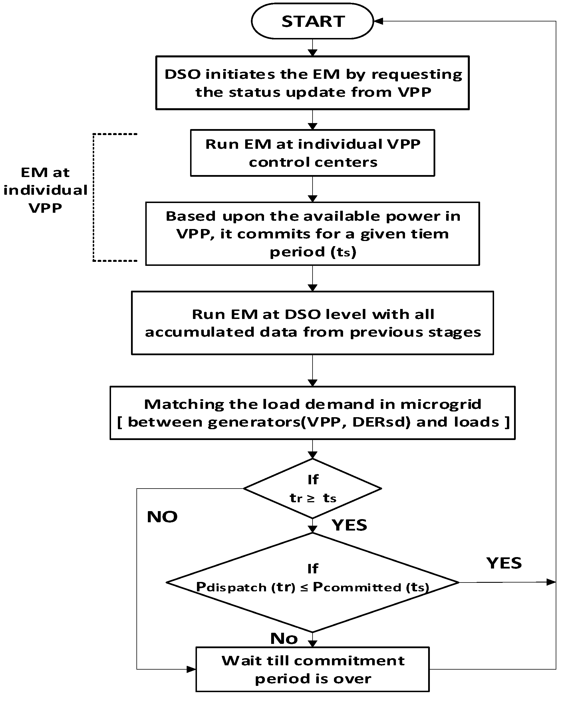
The Energy Management (EM) program in a VPP occurs in two major stages. In the first stage, an EM program is run at every VPP control center among the various available power generating resources and Energy Storage Devices (ESDs) in a VPP. This prepares a schedule for the available power with a VPP for a specified time slot, which VPP can commit to the distribution system operator (DSO) for carrying out the EM at the DSO level. In the second stage, at DSO level, an EM program runs between various VPPs, DERs and loads present in a microgrid. This prepares a dispatch schedule of available DERs and VPPs in the microgrid. The overall motive of an EM program is to dispatch the available power to the loads from different DERs in a cost-effective manner, adhering to the constraints of DERs, power transmission lines, and loads.
The first stage of EM, within a VPP can be formulated as follows. Consider a VPP having r, renewable energy resources (RES), m, ESDs, and n, Combined Heat and Power (CHP) plants that are dispersed and independent in operation while behaving as a centralized generating entity for grid participation and supplying power to DSO. The power from the renewable energy resources is the power available from non-dispatchable DERs. The power from ESDs and CHPs can be in the form of electrical and thermal power.
For a scheduled time period,
, the VPP control center fetches the maximum available power from the various DERs and DESDs as per (1) and (2):
where
is the maximum available power renewable energy resources,
,
,
, and
are the maximum electrical and thermal powers of energy storage devices, and CHPs respectively for the specified time period,
. The total power which the VPP commits to the DSO for participating in second stage of EM is the sum of electrical and thermal powers and is given as (3).
The power from the RES is the cumulative power obtained from non-dispatchable DERs such as PV, wind, and EV charging stations operating in vehicle to grid mode i.e., supplying power. In order to model the power from non-dispatchable DERs, uncertainty parameters associated with the non-dispatchable DERs has to be considered. The power from non-dispatchable DERs can be given as (4),
The power PPV can be modeled based upon the PV panel parameters and the amount of irradiance received during the scheduled time-period (
ts). The amount of irradiance is uncertain and the data can be obtained from the meteorological department in the area. Herein, α is the east to west inclination angle of panel,
β is the angle of irradiance. Further, the power PPV is given in (5), where
is the efficiency of the PV plant,
is the area exposed to solar radiation,
is the irradiance on the panel at an angle of α for a time period t
s obtained from meteorological data, and
β is the irradiance angle. The power from wind resource,
Pwind, is obtained from [
6] and provided in (6):
where
is the rated power of wind generator,
is the rated wind speed,
is the wind speed over which generation starts,
is the average wind speed over the scheduled time period, and is obtained from meteorological department. Aw is the total sweep area of wind turbine and
is the efficiency of wind power plant. It is worth noting that wind power is only possible if the wind speed is as per (7):
Flexible operation of EV is modeled as a charging and discharging mode of operations. In charging mode, EV consumes power from microgrid; in discharging mode, the power is fed back into the microgrid, which overcomes the scarcity of the local generation and meets the total load demand. The power consumed and discharged by EV at the charging station is formulated in [
26] and has been reproduced here as (8), (9), and subject to operating constraints of voltage and current limit as per (10) and (11), respectively.
As the cost of electrical power generated from ESD, PeESD is computed as the power supplied from battery as in [
27], as per (12)–(17).
The cost of power supplied by the CHPs is computed, as per (18)–(21).
At the EV charging station, the frequent charging and discharging flexibility of an EV battery might experience degradation to overcome this toll and to encourage EV participation in EM. As such, an incentive is paid to the EV owner in addition to the cost of discharging power. The net cost of an EV charging station as cost of power discharged and incentives minus cost of power consumed in charging, as in (22).
Due to the restrictions of maximum charging capacity and minimum (state of charge) SoC of the battery the EV battery energy level constraints are given in (23) and (24).
Apart from maximum available power from the DERs and DESDs in VPP, the VPP control center also fetches cost of power from the available resources and finally combines them as the cost of power from the VPP for that time interval, as per (25). Where is the cost of power from the VPP for a specified time slot . Based upon the total available power from the VPP, i.e., (3) and (25), the VPP commits the power and the cost of energy to the DSO.
For the second stage of the EM program, the DSO runs an optimal power flow program among the various available DERs, VPPs to supply the power to the loads for a specified time slot
as per (26). Furthermore, the DSO tries to maximize its revenue by minimizing the generating cost from the available power generating resources, as per (28).
Based upon the economic dispatch program, the DSO prepares a dispatch schedule for the DERs and VPPs participating in EM. This dispatch schedule is conveyed to the VPPs and DERs for maintaining the load supply. This is conveyed as the dispatch power to the VPPs, which is based on the power balance equation in (29).
Moreover, it should be noted that the dispatch power for the VPP must always be less than or equal to the committed power, as per (30).
The power supplied by VPP is the dispatch power. To meet this power, the VPP control center supplies part of it by harnessing the remaining renewable energy resources through other dispatchable DERs and DESDs. To maximize the profit share, the VPP control center runs an optimal power flow program for the remaining power to be fetched from dispatchable DERs and DESDs, as per (31).
The difference between the committed cost and the cost of the power generation from dispatchable DERs and DESDs is the net profit or revenue made by the VPP control center.
Based upon these formulations, the VPP control center runs the EMS program, shown in
Figure 1, and commits the grid for dispatching power as a virtual centralized entity by managing and controlling the dispersed DERs and DESDs in the local area. Further, the VPP coordinates with the MGCC or DSO operator to implement the demand side management and to demand response portfolio measures. Thus, in this manner, EM in the microgrid with VPP is carried out.
3. Mapping IEC 61850 Messages on XMPP
The VPP is powered from different resources that are usually owned by various plant operators. Usually, these plants are managed by the VPP control center through a communication network. This network is managed through a public network, i.e., the Internet, and presents network security challenges for the VPP communication network. Moreover, the intermittent DERs in a VPP are highly dynamic in nature. In other words, the constant change of the number of components in the VPP network creates scalability issues. To address these needs in VPP networks, a middleware technology is required to provide scalability and high network security.
Among several available protocols, eXtensible Message Presence Protocol (XMPP) web protocol is elected by IEC 61850-80-3 as the middleware solution for smart grids [
17]. The main reason is XMPP’s ability to manage several connections and providing cybersecurity.
In XMPP, simple authentication and security layer (SASL) and transport layer security (TLS) frameworks are used for the authentication and encryption process as specified by IEC 61850-8-2 [
23]. The recently revised edition of the IEC 62351-4:2018 standard specifies the cybersecurity requirements for the XMPP operational environment. The IEC 62351-4:2018 compliments the IEC 61850-8-2 security features by providing the recommended cipher suite to be used in TLS. The recommended cipher suite is: TLS_RSA_WITH_AES_128_CBC_SHA256. Specifically, RSA is for digital signature and certificates, AES 128 CBC is for encryption, and SHA256 is for Hash functions.
As specified by the internet engineering task force (IETF), XMPP is an open XML protocol where different clients of XMPP are connected with their respective XMPP server domains. A JabberID (JID) of the syntax “client_name@domain_name/IED(optional)” is provided to each member of XMPP server domain. Based on JID identity, the client-server model of communication is followed in XMPP communication technique.
As shown in
Figure 2, the Intelligent Electronic Devices (IEDs) of DERs and control center modeled by IEC 61850 are hosted by XMPP clients. All the XMPP clients in the local area are connected via an XMPP server with WAN and are provided a unique JID address. When any IEC 61850 client wants to communicate with the IEC 61850 server (or vice-versa), the MMS service initiated by the source control IED is wrapped in web protocol by its XMPP client. The source XMPP client connects to the XMPP server of its domain in WAN and exchanges data in the form of eXtensible Markup Language (XML) stanzas. The XML payload is composed of security elements wrapped around the encoded service PDU of IEC 61850 elements. In the following sections, we present the XML stanzas for client/server ACSI services.
Depending on the destination of the JID address, the XMPP server of WAN routes the XML payload to the XMPP client hosting target IED. The destination XMPP client unwraps the web protocol message and translates it as the MMS service to the receiver IED of IEC 61850. The XMPP client of the target IED again wraps the response MMS service PDU of IEC 61850 into the web protocol format and directs it to the XMPP server. Then, the server routes it to the XMPP client of the source IED, which unwraps the XML stanza and translates the service PDU to the IEC 61850 server or client residing inside, thereby confirming the communication process with security and scalability through XMPP middleware.
4. VPP EM with XMPP Communication
In this section, the information exchange and data flow for implementing the EM function is demonstrated. The EM considered in this paper is implemented through hierarchical control. DSO acts as central control and coordinates with a local VPP control center that facilitates participation of DERs in EM. The information exchange and data flow over XMPP protocol between various DERs, VPPs, and DSO for implementing the EM function are detailed in this section. Increased scalability and security are provided by the XMPP configuration deployment, making instant integration and effective coordination of multiple DERs possible in the VPP. As mentioned in
Section 2, the motivation behind EM is to dispatch the available power from various DERs to the loads in a cost-effective manner, considering the practical constraints of power transmission lines, DERs, and loads. The selected EM plan in this paper is realized in two stages. In the first stage, the estimation of available power with a VPP for a specified time slot (t) is calculated by running the EM program with different available resources in a VPP. Based on this estimation, VPP will commit to DSO for supplying available power in time (t). Whereas in the second stage, EM program runs between various committed VPPs, DERs, and loads at the microgrid or DSO level. This decides the dispatch schedule for VPPs and DERs at a microgrid level. In order to engage in EM information exchange between various participants in first stage and second stage at VPP and DSO, respectively, a XMPP communication network is established.
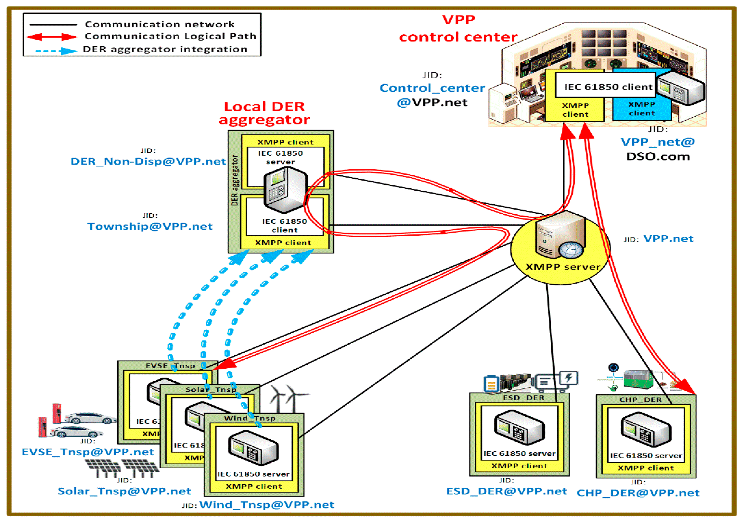
Depending on the hierarchical communication network, the XMPP server is located in a LAN or within a WAN, as per requirements. For the test system considered in this paper, each VPP system has one XMPP server, which coordinates intercommunication between IEDs of various DERs and VPP control center. A VPP test system consisting of DERs such as solar PV, electric vehicle supply equipment (EVSE), wind power turbines, CHP, and energy storage devices (ESD) station, along with their IEC 61850 control IEDs and XMPP communication organization, is illustrated in
Figure 3. For the purpose of aggregating multiple minor power resources belonging to same building, township, and shopping mall etc., a local DER management system within VPP can also be employed. The resulting intermediate virtual resource formed at local DER aggregator system will be hierarchically integrated to the upper level at VPP control center.
The VPP control center is deployed with XMPP server having a unique domain address. Hence, a single JID infrastructure is preferred in the first stage of an EM program, which is analogous to intranet communication architecture. A XMPP server of domain “VPP.net” is employed in the VPP test system considered in
Figure 3. The control IEDs of all DERs and intermediate DER aggregators act as XMPP clients, each of which assigned with a JID address belongs to a VPP.net domain. All the non-dispatchable DERs of facility are aggregated at IEC 61850 client (
[email protected]) and an IEC 61850 server of (
[email protected]) is provided to show them as a single power source virtually at the VPP. Finally, all the individual and aggregated resources of facility are being virtualized as a single entity at the IEC 61850 client (
[email protected]) of the VPP control center. Out of the two XMPP clients of VPP control center, one with JID “
[email protected]” is employed for internal communication, while the second one with JID “
[email protected]” is employed for commination between VPP and DSO.
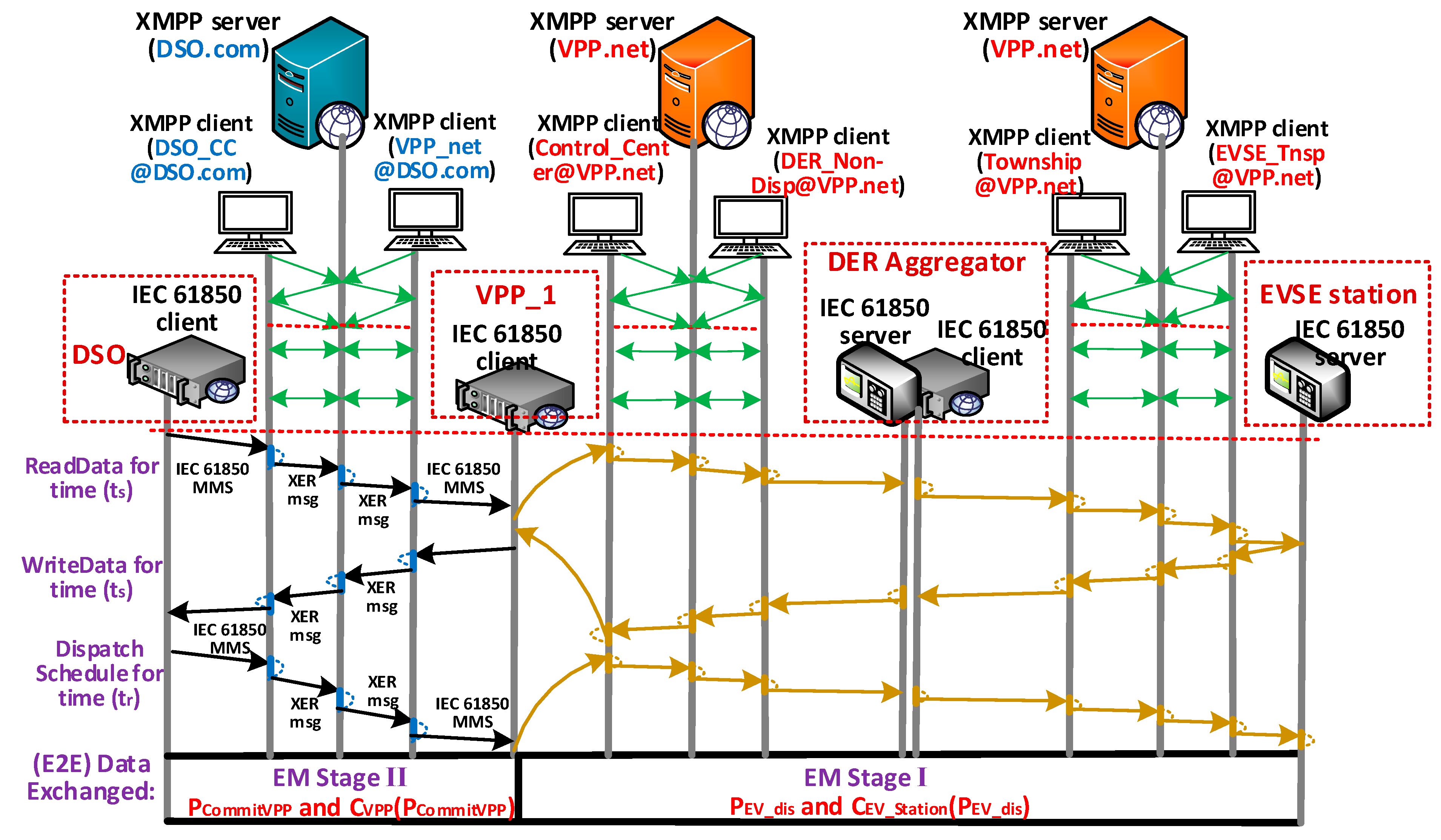
Inside the XMPP communication organization, the XMPP clients exchange the string of XML stanzas via the XMPP server of the same domain. Initially, a TCP/IP connection is established between the XMPP server and all the XMPP clients, over which a cryptographic protocol (i.e., TLS) is negotiated between XMPP clients and XMPP server for privacy and data integrity. Over the established TCP and TLS link, the XMPP clients and XMPP server negotiate a bidirectional XML stream in order to communicate and exchange the XML messages. The flow of message exchanges particularly between the VPP control center and CHP station during the process of EM is described in the UML flow graph of
Figure 4. After the TCP connection is established, the bidirectional XML stream is negotiated during E2E handshake authentication. As per EM in stage I, first the IEC 61850 client of the VPP controller requests the ReadData command so as to fetch the values of
,
, and
in time slot (t
s) from the IEC 61850 server of the CHP station. The MMS is first received by an XMPP client at the VPP center (with JID:
[email protected]), which wraps the message in a XMPP format, as per the XML encoding rule, i.e., XER message. Now, the current XML stream (i.e., XER message) is routed to an XMPP server (with JID: VPP.net) located inside the VPP using the JID address of a source XMPP client. The XMPP server then routes the XER message to the XMPP client residing at the IEC 61850 server of the CHP station using its JID address (
[email protected]). The XMPP client located at the CHP station unwraps this XER message and converts it to the primary IEC 61850 MMS message. In order to respond, the IEC 61850 server of CHP sends back the WriteData information; this MMS message is wrapped again in an XER message format by its XMPP client and routes it to the XMPP server. Finally, the XER response message is received by the XMPP client at the VPP center, which translates it to its original IEC 61850 MMS message format. Thus, CHP is committed to VPP for suppling of power
and
at a cost of
in time slot (t
s). After receiving the final dispatch schedule form DSO, the VPP calculates the optimum schedule for each DER in its vicinity. The CHP station participates in EM of VPP as per the final dispatch schedule received from the VPP for time slot of (
tr).
Table 1 shows the message flow exchanged inside the single JID organization of the VPP test system during the first stage of EM. In order to initialize the EM, the DSO control center first sends the power update command to VPP. Based on the status update command from DSO, the XMPP client located at DSO (
) initializes the XML stream to the XMPP client of VPP (
). Participating in EM, the VPP control center then fetches the update from available resources in its vicinity. As shown in
Table 1, the VPP control center (
[email protected]) commands the update of powers from all DERs:
,
,
, and their respective costs of energy:
,
, and
in time slot (t
s). In this regard, all the DERs of VPP, such as local DER aggregator (
), ESD system (
), and CHP plant (
[email protected]) start accumulating their available generation capacity.
Now, participating in EM stage I, the local DER aggregator inside the VPP commands the status update from the RES of the township project, including: EVSE “
”, solar facility “
”, and wind facility “
”. Based on EM Equations (5)–(9) and (22), the discharging incentive
, meteorological values of solar irradiance
and average wind speed (
), the values of
,
,
, and
are updated in the DER aggregator. Therefore, a collective power of
is estimated, per Equation (4) in
Section 2, by the IEC 61850 client of the aggregator “
”, which is updated as
at the IEC 61850 server of the aggregator “
”. The power
is the total amount of power estimated to be supplied by the RES of the township to the VPP through the local DER aggregator. In response to the VPP status update command, all the individual DERs (i.e., ESD system and CHP plant) and intermediate DER aggregator update the values of
,
,
,
,
, and
, respectively to the XMPP client of VPP at “
“, as per Equations (12)–(21) in
Section 2. Finally, in sequence to EM stage I, the VPP control center will commit the available power for a specified time slot at estimated costs to the DSO. Therefore, depending on the cumulative DER power and cost in Equations (3) and (25), respectively, VPP commits the bid of
at cost of
to the DSO.
At the DSO center, the dispatch schedule for the VPP is calculated based on the EM program in the second stage, which is allotted back to the VPP, as per Equations (29) and (30). Hence, the dispatch schedule of at a cost of for schedule time (tr) will be received by the VPP from DSO. In sequence to the EM program in stage I, the VPP control center runs the optimal power flow program based on Equation (31) to increase the share of its profit. In the end, the VPP control center allocates the final demand values of , , , and , to the ESD system () and the CHP plant (), respectively. However, the cost of RES, in schedule time (tr), is decided depending upon the maximum available RES power at the time of its discharge.
4.1. Multiple JID Infrastrcuture
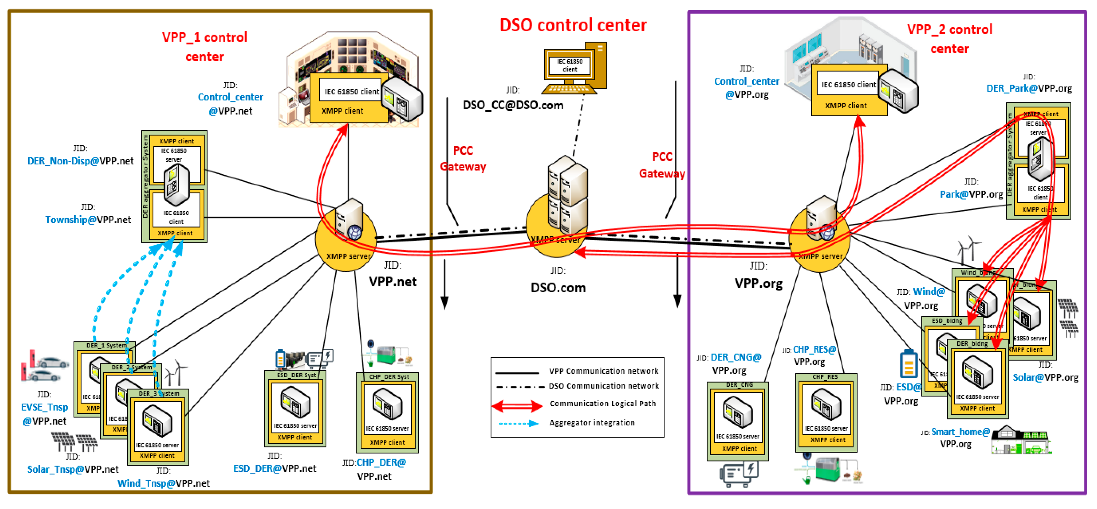
Analogous to communication architecture of the Internet, as shown in
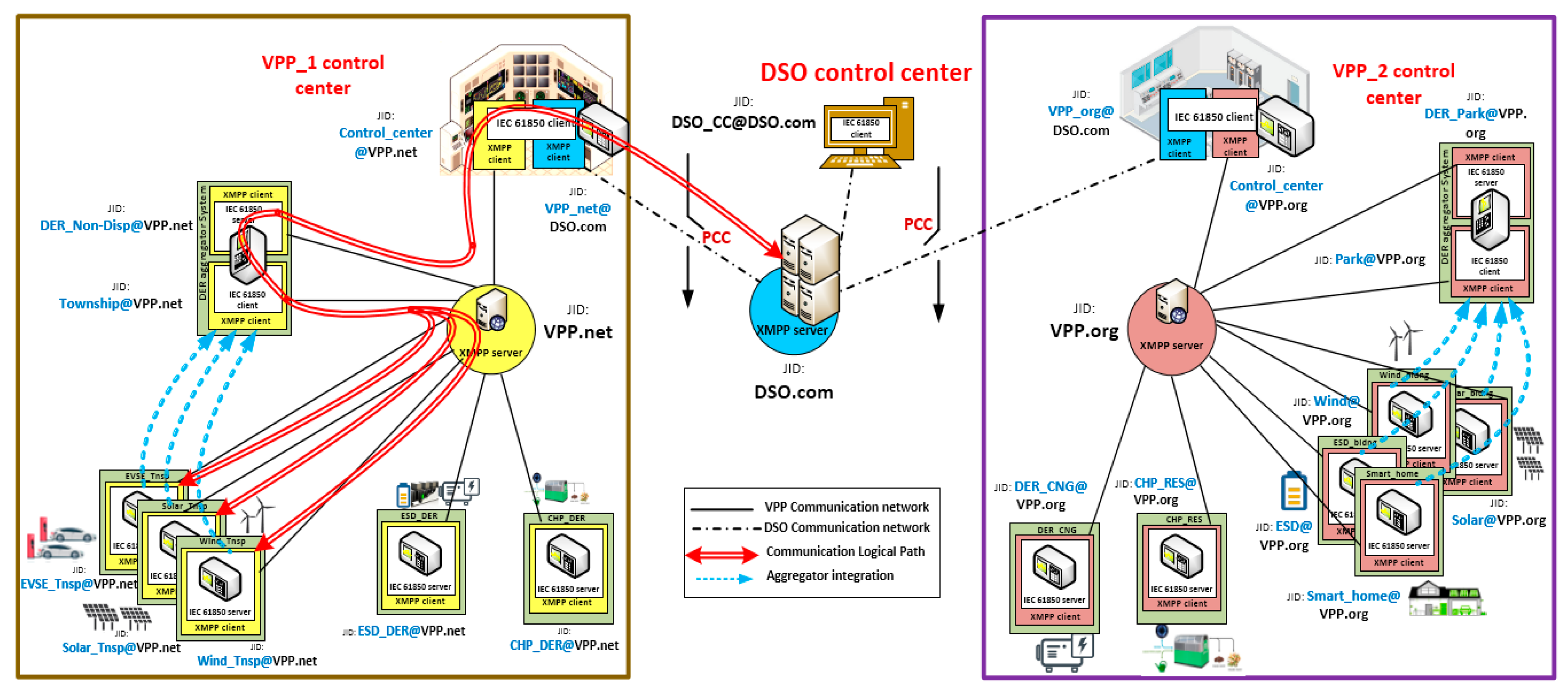
Figure 5, multiple XMPP JID infrastructures is deployed, where the EM program will run in two stages simultaneously, in the case of interdomain communication among two different VPPs and DSO operators. The test system considered in
Figure 5 hosts a total of three XMPP servers with JIDs of DSO.com, VPP.net, and VPP.org. Either the VPP control center or the individual DER resources can employ more than one XMPP client belonging to a different domain to get access across the interdomain XMPP configuration. The IEC 61850 client located at DSO control center (
[email protected]) can neither see, connect, monitor, or subscribe to the presence of any individual DER resource in either the VPP facility microgrid, due to the fact that DSO and VPP belongs to different JID configurations. The DSO control center can get access to a local DER aggregator or individual DER inside the VPP facility, but only if the VPP is configured with a JID belonging to a DSO.org domain, in addition to the JID of VPP.net or VPP.org. The test system considered in
Figure 5 follows multiple JID domains involved in XMPP communication. Its organization of the two VPPs and DSO are as follows:
DSO.com: the domain of XMPP server belongs to distribution system operator (DSO).
VPP.net: domain address of XMPP server belonging to the first VPP control center.
VPP.org: domain address of XMPP server belonging to the second VPP control center.
The message exchanges for EM in multiple JID infrastructure between DSO operator, two VPP control centers, DER aggregators and local DERs is demonstrated in
Table 2. The IEC 61850 clients of VPP control centers are deployed with XMPP client belonging to DSO.com, in addition to their local domain XMPP client. Therefore, a single large entity representing an entire VPP facility can be virtualized at the IEC 61850 client of first and second VPP control centers with a JID:
[email protected] and
[email protected], respectively.
As discussed above, information flow and message exchanges take place at each individual VPP in the first stage of EM with a single JID communication, as per
Table 2. After DSO-based EM initiation, with a status update command to VPP_1 and VPP_2, both start fetching updated values of available energy from the DERs inside the VPP. After successfully receiving the available power and cost information from all the DERs within VPP, both the VPP control centers estimate the aggregated sum of available power for a specified time slot (
) and for the estimated costs to the DSO. Based on the cumulative DER power Equation (3) and cost Equation (25) mentioned in
Section 2, the VPP_1 (
) and VPP_2 (
) commits the bids of
at cost
and
at cost
respectively to the DSO (
).
In the second stage of EM, the DSO calculates the optimal schedule, as per Equation (26), and the minimum cost, as per Equation (28). Therefore, by comparing both the bids in Equations (26) and (28), the DSO allots the VPP_1 () and VPP_2 () regarding the dispatch schedule and time. Depending on economic dispatch and availability constraints in the schedule time interval as per Equations (27), (29), and (30), the values of at cost of and at cost of are dispatched to and , respectively by the . Ultimatley, as per the dispatch schedule of VPP_1 and VPP_2 for the schedule interval (tr), each VPP assigns the optimal dispatch schedule to all of its local DERs, respectively, as per (31). The net revenue made by VPP_1 and VPP_2 is calculated as difference between , and , respectively.
Similar to the EM shown in
Table 2,
Figure 6 demonstrates an example of multiple JID information exchanges between the IEC 61850 client of DSO and the IEC 61850 server in the EVSE station. Herein, the IEC 61850 client residing in the XMPP client at DSO first generates the MMS message in order to update the status of VPP_1. The XMPP client (with JID:
[email protected]) wraps the MMS message in the XER message format and routes it to the XMPP server of DSO (with JID: DSO.com).
In order to exchange the information from one XMPP domain (JID: DSO.com) to another XMPP domain (VPP.net), the corresponding IEC 61850 client/server needs to have two different XMPP clients for each domain. Particularly, in the case of
Figure 6, the IEC 61850 client of VPP_1 has two XMPP clients:
[email protected] and
[email protected] for integrating with XMPP servers of DSO and VPP, respectively. After receiving the status update command from DSO through the XMPP client (JID:
[email protected]) of VPP_1, the IEC 61850 client of VPP_1 fetches the current status of all DERs in its vicinity.
When exchanging messages between the VPP_1 and EVSE station, the process of EM used in the first stage of a single JID organization is repeated, as it is in
Table 1 and
Figure 4. After receiving the power and cost values from all the DERs, VPP_1 commit to DSO for suppling power of
at cost of
in time slot (t
s). The MMS message of IEC 61850 client of VPP_1 is wrapped into an XML encoding format by the XMPP client (JID:
[email protected]); the XER message is then routed towards the XMPP client of IEC 61850 client (JID:
[email protected]) residing at the DSO center. The final dispatch schedule for time slot (t
r) is sent back to VPP_1 after performing the DSO level optimal flow considering multiple VPPs and DERs involved in microgrid. Similarly, all the message exchanges involved in EM of DSO along with VPP_1 and VPP_2 are listed in
Table 2.
4.2. Multiple Domain Resources With Federation Link
The access and control of resources in multiple XMPP domains is possible through the deployment of more than one XMPP clients at each VPP. Maintaining two streams over the single physical layer related to presence stanza and ROSTER information of each client significantly decreases the bandwidth. Moreover, the XMPP mechanism for instance PubSub (Publish–Subscribe) that used to share the monitoring information of multiple IEC 61850 clients cannot be used to reduce bandwidth consumption. Thus, due to the limitations of bandwidth decrement, coordination complexity and limited access provision, multiple JID configuration is not preferred for highly distributed multiple VPP and DSO coordination. Instead, as per IEC 61850-8-2, a federation link is established between different XMPP domain servers, as shown in
Figure 7. Through the federation link, the same XMPP clients located in different domains made to communicate with each other via XMPP servers in between. For any incoming XML stream, the XMPP server first resolves the domain address (as indicated in the destination field of XML stanza), then routes the XML stream to the XMPP server of the target domain. The federation link established between the XMPP servers of VPP.net, DSO.com, and VPP.org domains provides the inter domain communication access through the permission of forward routing by XMPP servers, depending on the deployed role-based access control (RBAC).
As demonstrated in
Table 3, the federation link established between the XMPP servers of the test system leads to communication between the control IEDs of various DERs, VPPs. and DSO. Unlike in earlier cases, the XML stream of DSO controls IED in case the federation link is forwarded to the XMPP server of
from the
through the federation link between the two servers. Therefore, the communication between control IEDs
,
and
is established without installation of multiple domain XMPP clients at the control centers of VPP_1 and VPP_2.
Furthermore, with provision of federation link, the DSO_CC can make direct communication with local DERs and DER aggregators of the VPPs, as given in case II of the federation link. In such a case, a prior agreement is made between the VPP and DSO control centers to share the energy of resources. The red line communication path between DSO and DER park of VPP_2 in
Figure 7, describes that
is directly communicated through
. It is assumed that
is under prior agreement with the DSO_CC and VPP_2 to share the amount of energy as per requirement. In order to update the real time status of neighboring VPPs and make them participate in forward market agreements, possible communication between the VPP_1 and VPP_2 is shown in case III of the federation link. Though the XML stream flows via the XMPP server
, the participation is limited to control IEDs of the
and
. Consequently, the limitations of bandwidth decrement and complex coordination have been overcome with the federation link XMPP message exchanges. Therefore, scalable, secure, and effective coordination between DSO, VPP, and DERs in different stages of EM is realized with the presence of XMPP middleware communication configuration.
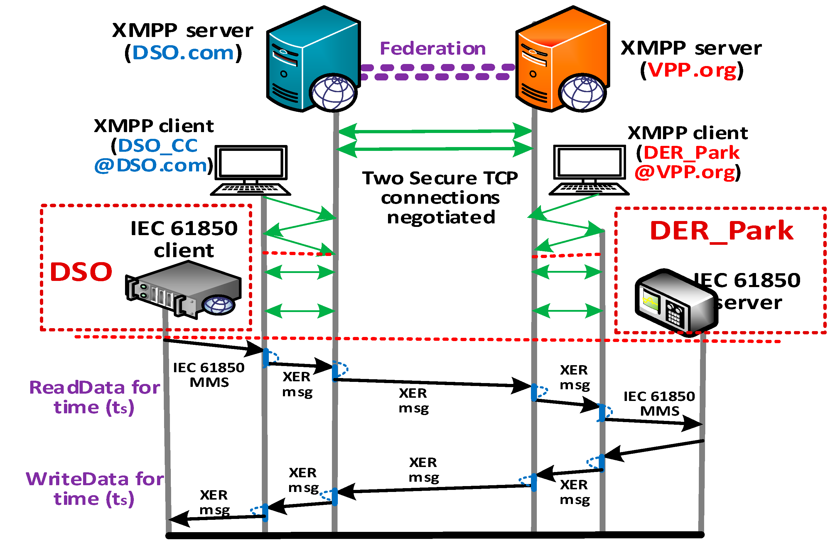
As described in
Table 3, case II,
Figure 8 shows the communication establishment and message exchanges between the DSO center and DER aggregator of VPP_2 (i.e., DER_Park). The federation link established between two XMPP servers, DSO.com and VPP.org, facilitates the direct communication between the two servers without having extra XMPP clients for each domain. Two or more TCP connections are established for the number of streams, providing security to each separate stream. This type of federation-based interchange is useful in highly distributed scenario involving multiple VPPS, DERs, and DSO, as the amount of wastage in bandwidth is low and when complexity is significantly reduced. Similarly,
Figure 9 describes the message flow between VPP_1 and VPP_2 via federation link provided between the three XMPP servers i.e., VPP.net, DSO.com, and VPP.org respectively.
5. Conclusions
Deep penetration of renewable and storage devices, including electric vehicles, needs advanced coordination in smart grids. The concept of VPP lends itself to such implementations as it can group different components and optimize their operation. However, this energy management concept, i.e., VPP, requires an effective communication infrastructure that enables information exchange between different types of equipment over a large geographical area. In other words, the VPP communication network is versatile enough to easily accept new deployment and achieve security over a wide-area network. This is particularly relevant as cybersecurity concerns have taken a front seat in power system operation plans due to recent awareness.
To address this pressing need, this paper implemented VPP EM with IEC 61850 models and messages. Using this communication standard for power systems makes the developed EM very versatile and strong. To achieve scalability and security in this standardized network, XMPP is implemented as a second layer. XMPP based information exchanges have been developed and demonstrated.
Since there are multiple plants in a VPP that belong to different entities, it is certain that the communication would require multiple XMPP domains. A multi-federation solution for XMPP based VPP communication has been developed and showcased.
In addition to aforementioned contributions, this paper shows how the use of XMPP can facilitate connecting different power system components over a wide area network while addressing cybersecurity concerns. This will motivate researchers, grid operators, and vendors to consider its use not only for VPP but in other cases, such as microgrids or electric vehicle charging coordination.

 ,
, 


