Incremental modeling aided by loop-shooting: In the initial 3D model scene, the missing region of the model is searched and the set of loop-shooting images for the missing region is acquired. The optimal results are then reestablished through iterative incremental fitting based on aerotriangulation theory, using the corresponding model of the missing region.
Accuracy verification and model modification: The accuracy of the 3D reconstruction results aided by loop-shooting is first verified; then, the reconstruction model (including uniform color, tensile, leveling and deletion) is refined, and finally, the completed 3D model is exported.
3.2.1. Incremental Modeling with the Aid of Loop-Shooting
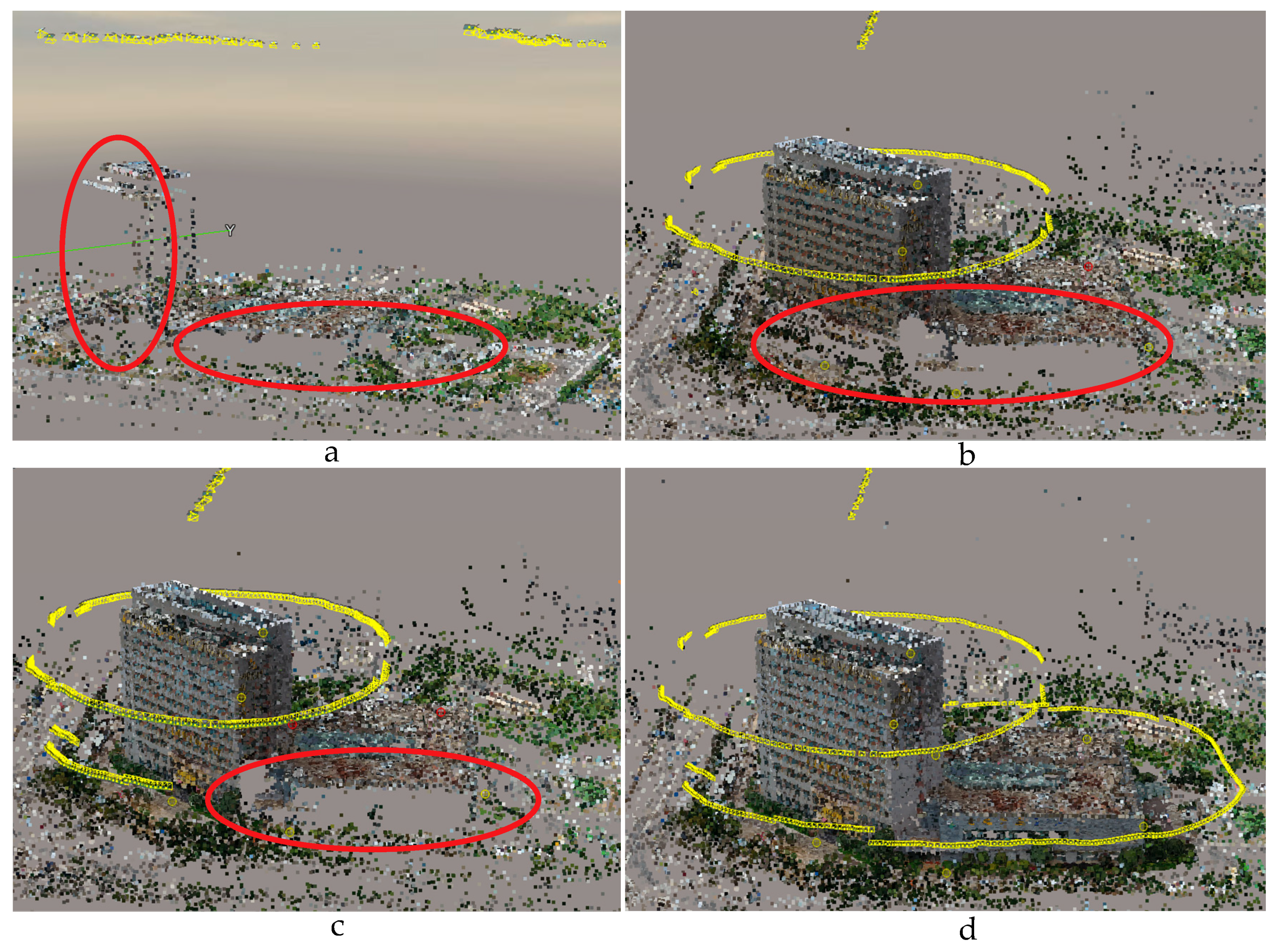
Initially, some details of the 3D model scene are missing. These missing details occur because the image series lacks some of the specific images required to present the complete model scene. The key aspect of loop-shooting-aided reconstruction is to increase the number of point clouds in the detailed parts of the model. The incremental iterative solution is conducted to increase the number of point clouds by combining the loop-shooting image set with the initial aerotriangulation results. At the end of these calculations, the external orientation element and the ground 3D coordinate points under the loop-shooting 3D triangulation (conducted specifically to increase the number of point clouds in the defective region) are obtained. This loop-shooting incremental iterative aerotriangulation process continues until all the defective areas have been repaired, resulting in an optimal reconstructed aerotriangulation to generate the 3D model of the entire scene. The specific procedures are as follows:
Step 1: Detect model defect areas. Based on the initial 3D model, model defect areas (which include occlusions, distortions, and void areas) are detected by the geographic location method [
31]. The precise geographical location of each defective region is recorded.
If the scale of the model scene is relatively large, GNSS-aided positioning is adopted. The calculation is shown in the following equation:
where
S is the set of all defective regions in the initial model scene and
sj is the
jth defective region
s.
After obtaining all the defective regions
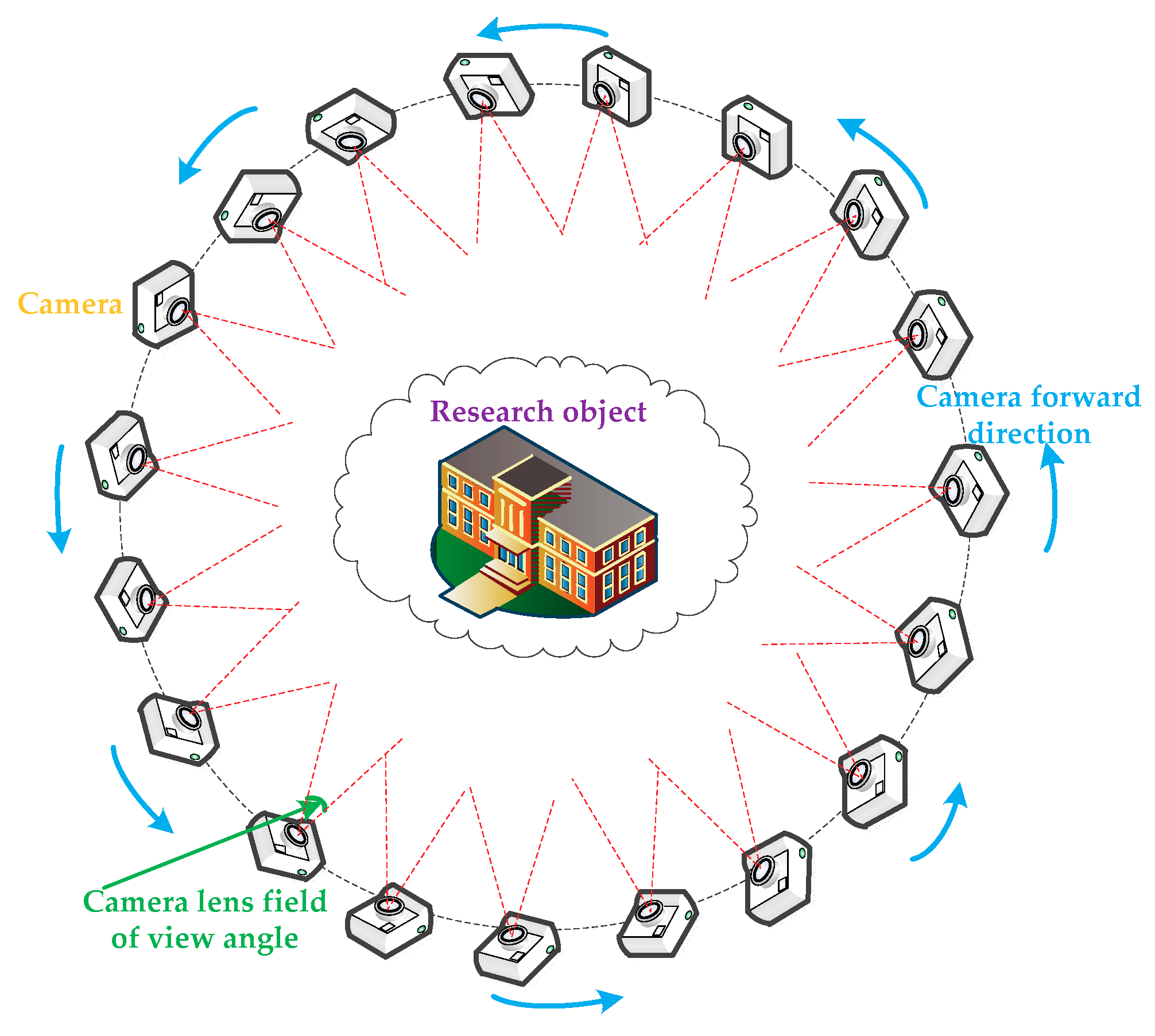
S by Equation (1), the loop-shooting images of the defective region are acquired. When acquiring the loop-shooting images, a 360° forward mode is adopted to ensure that the loop-shooting directions are consistent. After the images are taken, the
nth loop-shooting image set is denoted as
RIn. A schematic flow chart of the loop-shooting process is shown in
Figure 5. While acquiring images, the overlap rate must be ensured in every two adjacent images (such as a 75% overlap rate). In addition, the acquisition process must ensure that a sufficient number of matching points will exist between the loop-shooting images and the original UAV images. The specific strategies adopted are as follows: select an image in advance to calculate the corresponding matching points using a threshold of 70% of the total image matching points. Then, determine the matching points of the other loop-shooting images. Image whose matching points exceed the threshold are retained; the others are deleted.
Step 2: Calculate the exterior orientation elements of the loop-shooting images. The geographical spatial location is determined by the selected loop-shooting images. The exterior orientation elements of the loop-shooting images are calculated by space resection [
32]. In detail, the relationship between the object space coordinates and the image point coordinates are established by direct linear transformation and the colinear equations are constructed [
33]. To solve the collinear equation and obtain the initial external reference values of the loop-shooting images, at least 6 control points are placed in the object space (in this paper, 7 control points are used to solve the collinear equation). The purpose of the collinear equation is to establish the correlation between the ground point, the image point, and the projection center [
34,
35].
The mathematical expression is as follows:
where (
x,
y) represents the image point coordinate; (
x0,
y0) represents the coordinate of the principal point of the image; (
X,
Y,
Z) represents the ground point corresponding to the image point coordinate; (
XS,
YS,
ZS) represents the projection center coordinate; and
represents the matrix of the rotation transformation.
After a series of derivation transformations, Equation (2) is calculated as follows:
The coefficients of li can be calculated by the ground control point and the corresponding image point. There are 11 coefficients in Equation (3); therefore, solving it requires a minimum of 6 control points.
After solving Equation (3), to ensure the robustness and precision of the external parameters, the initial external parameters are optimized by the space resection algorithm, whose core purpose is to “extrapolate” the exterior orientation elements of the loop-shooting images through the 3D triangulation results.
Step 3: Update the coordinates of the 3D triangulation results. After adding the loop-shooting images, new matching relationships can be calculated. In other words, after obtaining the exterior orientation elements of the loop-shooting images, the new 3D point coordinates are obtained by a multi-image forward intersection [
36]. To improve the reliability of the model points, they are filtered by the size of the intersection angle between all the light rays corresponding to the 3D points. Then, the 3D point coordinates in the region are updated. This process ensures that the 3D triangulation results and the loop-shooting images are both located in the unified coordinate system.
Step 4: Optimize the results of the 3D triangulation. The loop-shooting images, the 3D point coordinates from Step 3, and the initial 3D triangulation results are combined, and the bundle block adjustment method is conducted again to generate a new point cloud. To ensure the accuracy of the results, an incremental adjustment calculation is applied, and the corresponding errors are eliminated after each adjustment.
Specifically, after the new 3D triangulation results are calculated by the bundle block adjustment method, the corresponding errors are eliminated based on the root-mean-square error (RMSE) distribution of the reprojection error. First, the median reprojection errors are set to be the minimum threshold , and the 1.5-fold value of the median is set as the maximum threshold . Then, the RMSE values of the reprojection, T, are statistically analyzed for each image. When T is smaller than , the image is retained, and when T is greater than , the image is discarded. When T is between and , the RMSE of reprojection of the two neighboring images (those directly adjacent to this image) are analyzed to determine whether they are significantly different: When the difference is large, the image is discarded; otherwise, it is retained. After this judgment has been completed, based on the adjusted 3D triangulation results, we continue to conduct the next adjustment calculation until the threshold condition is satisfied. At the end of this process, the loop-shooting image set adjustment is complete, and the process is repeated from Step 1 to Step 4 with the next defective region.
Step 5: Incremental computation to obtain the optimal solution 3D triangulation. After optimizing the results of the 3D triangulation, the set of model defective regions,
S, is detected. If the defective regions of the model are not completely repaired, more loop-shooting images are added, and Step 4 is repeated. The mathematical expression for this process is as follows:
where
xn is the aerotriangulation result after the
nth incremental iterative calculation,
is the image set from the
nth loop-shooting, and
x0 is the initial results of the aerotriangulation.
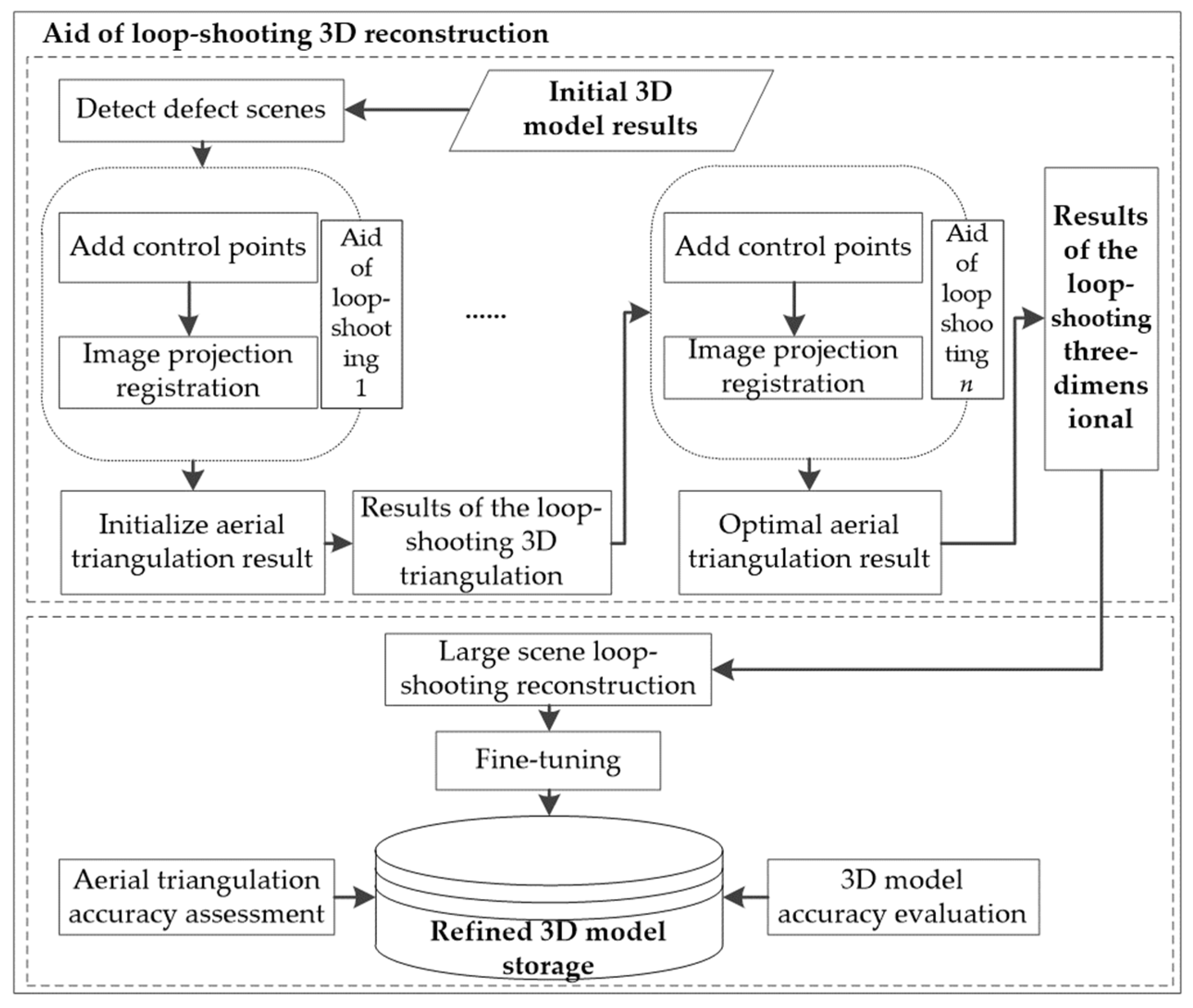
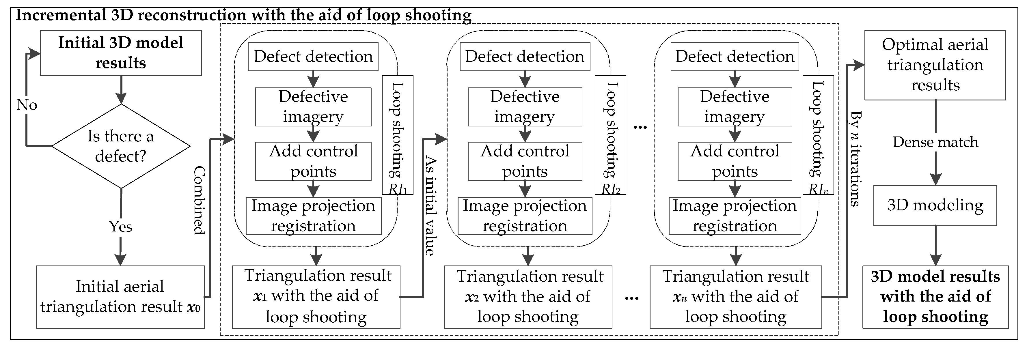
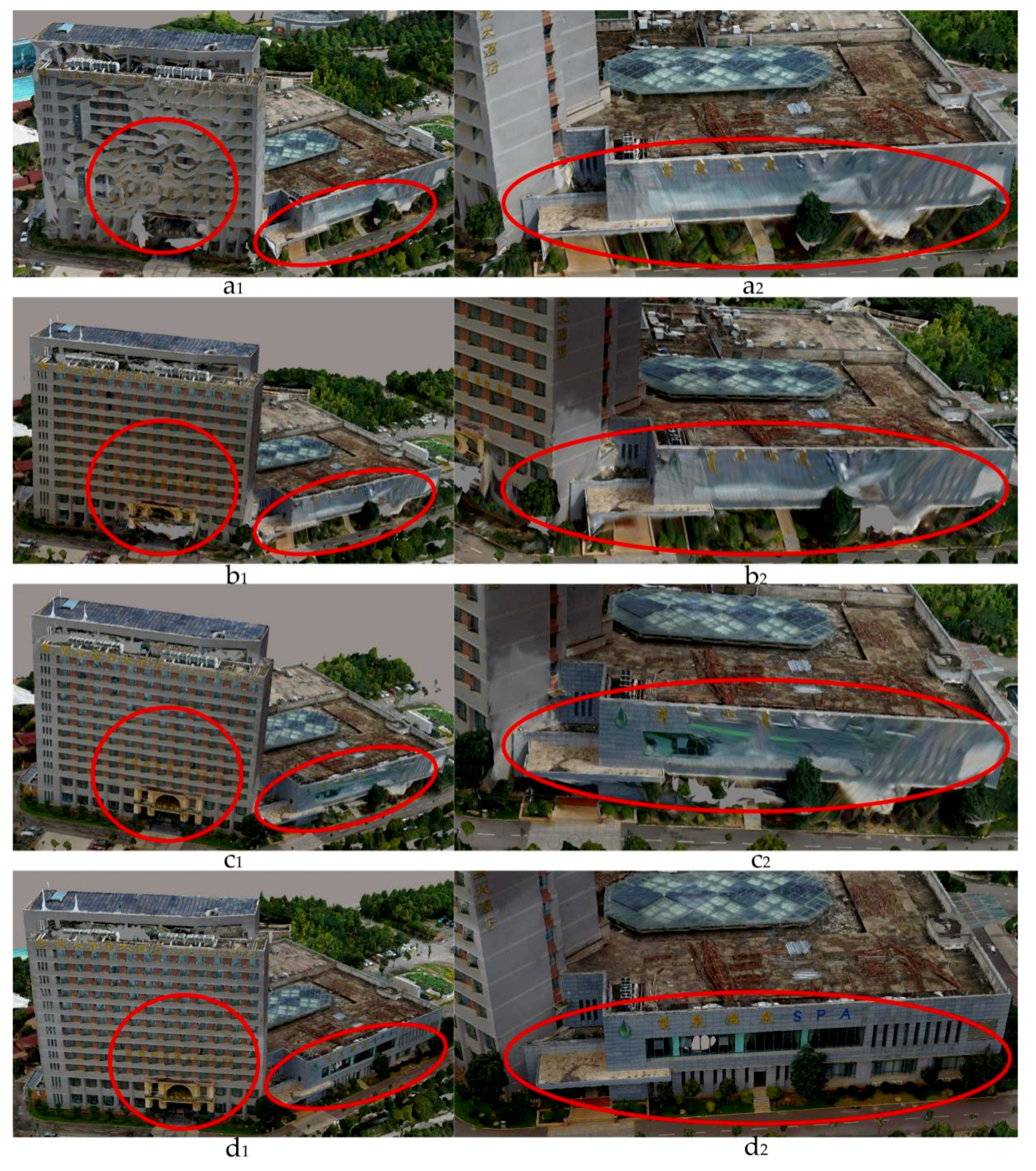
Through incremental optimization calculation (i.e., Equation (4)), after all the defective regions of the model have been repaired, the results of this loop-shooting 3D triangulation are taken as the optimal 3D triangulation result. Finally, incremental calculations aided by loop-shooting are halted, and the optimal results of the loop-shooting-aided 3D triangulation are saved.
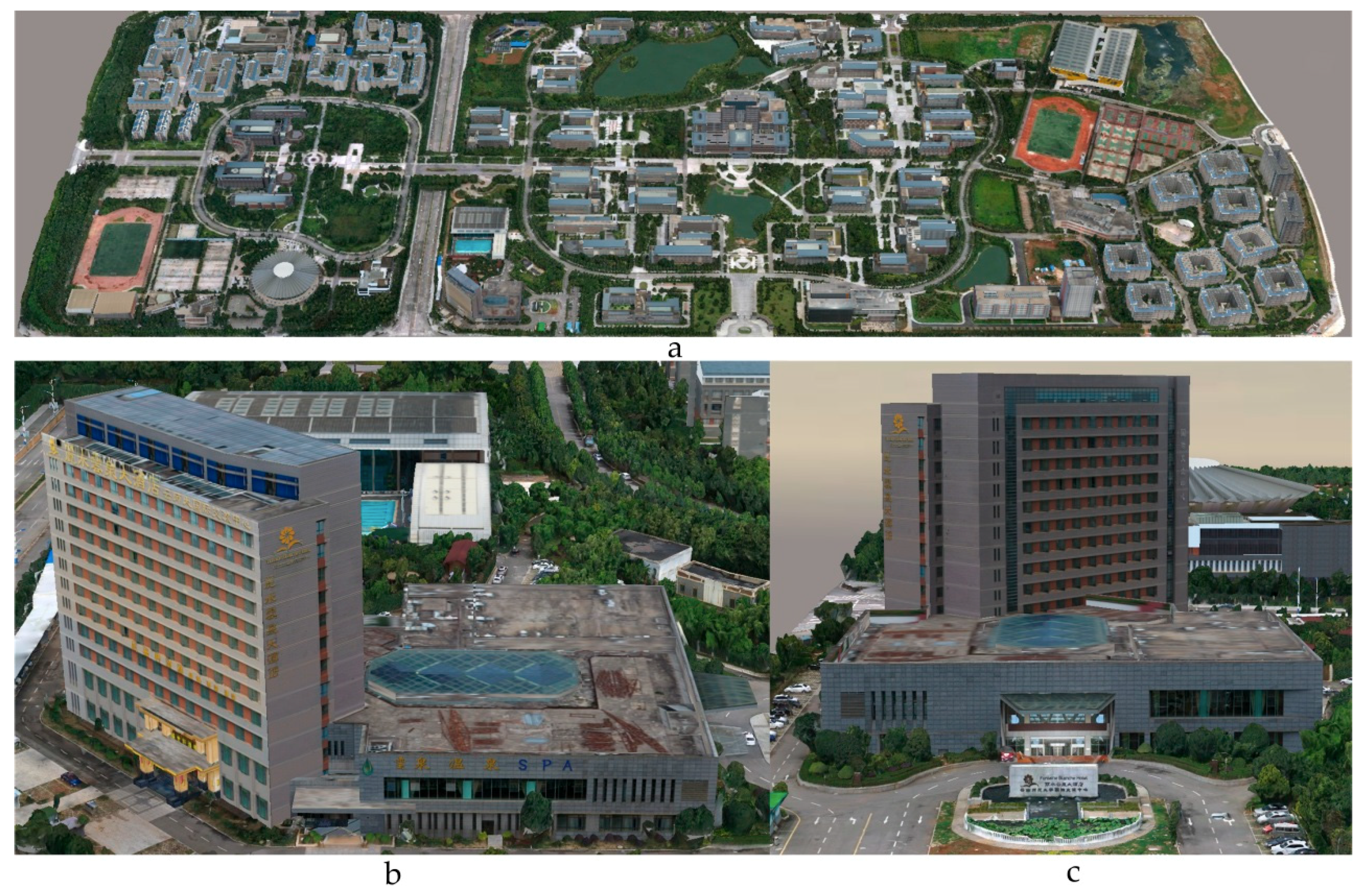
Step 6: The 3D reconstruction of the optimal loop-shooting-aided 3D triangulation. Based on the optimal loop-shooting-aided 3D triangulation results, dense matching is used to construct the DSM model, and textures are mapped to generate the reconstructed 3D model.
A flowchart of the entire loop-shooting-incremental 3D reconstruction process is shown in
Figure 6.


